When you click on links to various merchants on this site and make a purchase, this can result in this site earning a commission. Affiliate programs and affiliations include, but are not limited to, the eBay Partner Network.
The original cluster on my '67 has been on the list of things to do since I got the car, but that was a "down the road" project until I saw a dash assembly on eBay that had a full compliment of options, including cruise and the rear defogger switch. I got the cluster with the idea of removing and restoring each piece and when it came time, swap it as directly as I could with my original. I really want that rear defogger option.
Here is the original condition in which I received it - looks like it was stored in a dry lake bed...
After my experiences with wiper switches and radios, etc., I figured some extras to practice on and/or repair would be a good thing.
It's a simple removal process to pull the switches and the gauges from the main face plate.
I used warm water and a microfiber cloth as well as a Q-tip to clean the dirt and dust from these without scratching the faces.
Be careful at this point to not lose or damage the flimsy colored plastic lenses that say HIGH BEAM and BRAKE as well as the green blinker lenses. Take a quick pic of where and how they sit. The plastic lens over the whole gauge cluster is just sitting in place with rubber strips underneath to keep it from rattling against the metal. I used warm water and a plastic polish applied carefully by hand to rub out the amazing amount of scratches. As I removed pieces, I reinstalled the 1/4" hex screws back where they came from so I wouldn't lose them.
The whole cluster is chromed, and the original texture finish black just fell off with a little effort and a Scotch Brite pad. Some areas are smooth flat black, such as around the AC controls and the vent/clock circles. Now it's all about masking the areas you want to protect from texture paint. I applied the tape snugly around all the edges and used a razor blade to trim where the chrome edges should show. This took quite a few tries, as it's super easy to slip with the blade and cut away your protected areas (or your fingers - be careful). I used VHT texture paint, and you really should use a heat gun for drying and creating the wrinkle effect.
The key to success with the texture paint is even coating and even drying with heat. The heavier you apply the paint, the larger your wrinkles will be. I applied moderately, using just enough paint to cover the chrome fully, trying not to over-apply in corners and tough to reach areas. Drying with the heat gun just takes a little patience - hold the gun 18-24" away from the piece on high setting, moving the nozzle in a circular motion and not pinpointing any particular area. After a few minutes you will see the paint start to "flash off" - become dull and wrinkle. Once that starts, follow the drying pattern across the piece until the whole area is evenly dull and wrinkled. You'll understand what I mean when you see it happen.
I noted that after one application there were some heavy and light spots seen, so I dusted the entire surface once more with the paint and did the heat drying once more. The second coat turned out exactly as I wanted it to look.
In this pic you can see the left side has started to "flash" while the right side is still fully wet. You'll be able to see the paint change quickly once this effect starts.
Once everything sat for a few hours, I pulled the tape and was happy with the final result. If there are any spots that need trimming or touching up, you can use a paint brush and the heat gun again, or a razor blade to even a line.
At this point I turned to cleaning the gauges and switches on the cluster. Several I dropped in Evaporust for a good soaking - the electric switches are internally mechanical, so don't worry about getting them wet. Just make sure they're dry in the end before use. I used chrome polish and microfiber cloths as well as a Dremel with a wool wheel to shine up the plastic chrome where needed. I posted another thread on how I repaired and refreshed the clock. I cleaned an extra Heater/AC control that I had (also another thread on how I removed and repaired the TEMP ****). I dismantled the cruise and defogger switches and polished the *****, and cleaned the ignition switch, which for some reason seems to be new on this panel.
I cleaned the circuit boards with soap and water and in some cases a Magic Sponge to polish up some electrical contacts. I ensured all the pins were solid. I replaced all the 168 blubs with LED's and the testing of the appearance was excellent - I can't wait to see these in the car.
Then reassembly was the opposite of disassembly - no tricks or anything crazy here.
I found 1/4" self stick weather strip on Amazon for $5 - cut to fit for the clear lens
Self stick pieces in place between gauges and on either side of the speedo
Cluster plastic sets in place
Whole cluster fits back in place and can be tightly mounted with the original screws
At this point I compared light bulbs, as I have heard conflicting things on white versus color LEDs. The stock 168 bulb was bright, clear, but had an unevenness to the light that was "fixed" by using the white LED bulb. A green LED was FAR too bright - "brash" might be a good word to use. Could have been the brand I chose or just the brightness of this particular green, but I'm staying with the white LED on the whole cluster.
Final shots
Temp needle flipped when I touched the wrong pin on the back side and shot 12V to it - oops. All good in the last pic
I have a different radio that is being restored to fit in the hole - also the courtesy light switch will come from my current cluster.
Done for now - when the original cluster is removed I will transfer over a few things and slip this right in its place.
Last edited by BSiegPaint; January 6th, 2024 at 09:35 AM.
Bob, impressive patience, and diligence you demonstrated during this dash redo. The end result is impressive—very nice work, and something I know you are proud of. Thanks for sharing the experience with others.
Great job! You have way more patience than I do now. Years ago I wouldn't have thought twice about tackling that.
Looking forward to seeing it with that refurbished Wonderbar installed. It'll be 1967 all over again!
Wouldn't you love to have been the individual who assembled instrument panels all day at the factory?
The one thing I'm always amazed at is the care I have to take to not scratch or dent or mar anything like this that I'm working on, and I always wonder how they did that on a fast assembly line...! There's always something I mess up and have to repair. I should have the radio back in a couple weeks! I'll make sure I fire it up and send you a video clip
Great work! I just did the exact same restoration on my '66's panel.
One recommendation I can make though is to double check those pins on the back of the gauges. Some of mine were loose.......just loose enough to lose the connection occasionally. Also, I came up with a bench test to double check all the gauges (specifically the temp, fuel, and ammeter). I can post how I did that if you like. I feel a lot more confident putting the panel back in knowing the gauges work.
My Wonderbar AMFM radio works ok, except for the signal seeking. It gets stuck at the end and you have to wack it for the mechanism to return to the beginning. I'm thinking about just getting it converted to modern internals with the Aurora upgrade stuff.
Last edited by ourkid2000; January 6th, 2024 at 04:59 PM.
Great work! I just did the exact same restoration on my '66's panel.
One recommendation I can make though is to double check those pins on the back of the gauges. Some of mine were loose.......just loose enough to lose the connection occasionally. Also, I came up with a bench test to double check all the gauges (specifically the temp, fuel, and ammeter). I can post how I did that if you like. I feel a lot more confident putting the panel back in knowing the gauges work.
My Wonderbar AMFM radio works ok, except for the signal seeking. It gets stuck at the end and you have to wack it for the mechanism to return to the beginning. I'm thinking about just getting it converted to modern internals with the Aurora upgrade stuff.
I would love to learn your gauge bench test procedures. I agree it would be best to know everything is in perfect function before hooking it all up in the car. I'm having Jim Shepard in Scottsdale do the resto on the Wonderbar - he's done some great work for me in the past on my Rallye and 442 radio and 8-tracks.
I would love to learn your gauge bench test procedures. I agree it would be best to know everything is in perfect function before hooking it all up in the car. I'm having Jim Shepard in Scottsdale do the resto on the Wonderbar - he's done some great work for me in the past on my Rallye and 442 radio and 8-tracks.
I've got a full set of spare gauges. I'll hook em up on the bench and take some photos of how I tested them.
You'll need a power supply (a battery would work fine I suppose), some test leads, and some resistors. I used a decade box, as a substitute for the sending units, but it's not necessary. The fuel gauge uses ~ 1 - 90 ohms and the temp gauge uses around 50 ohms all the way up to approx 800 ohms. I used a spare Toronado headlamp in series with the ammeter to check that particular gauge. *edit* You'll need some way of limiting the current with this test. I used a variable power supply and had dialed the voltage down to a little less than 2v to get the headlamp to pull around 1.5A. I should have mentioned this, sorry.
Actually, I never did determine what the proper full deflection amperage was on the ammeter as I'm not 100% sure if both of mine are accurate, It will be very interesting to see what yours pulls. Mine was full deflection at about 1 amp.
Last edited by ourkid2000; January 6th, 2024 at 09:19 PM.
Absolutely outstanding - I have a decade box in the basement and I'll pull that out to set this up. THANK YOU!!!
I'll double check the testing of the temp gauge tomorrow. It uses the same pin for the power supply (pink wire) and I think it uses the dark green pin (so second from last going outboard to inboard) as the variable connection to the sending unit. Same ground connection as well but I'll double check it for sure.
So fellers.....what do you have for wire colors on the inboard cluster connector? This would be the ammeter, oil pressure light panel. I ask because mine in my car do not match what is shown in the wiring diagram in the '66 CSM. My outboard cluster connector does match, however.
The manual says it should be Blk-Wht | Tan | Black | Gray | Drk Blu | Pink | Blank | Drk Blu w/ wh stripe
Mine is this (I actually can't confirm what the colors are because my color vision isn't great. I know they don't match though):
Last edited by ourkid2000; January 9th, 2024 at 08:54 PM.
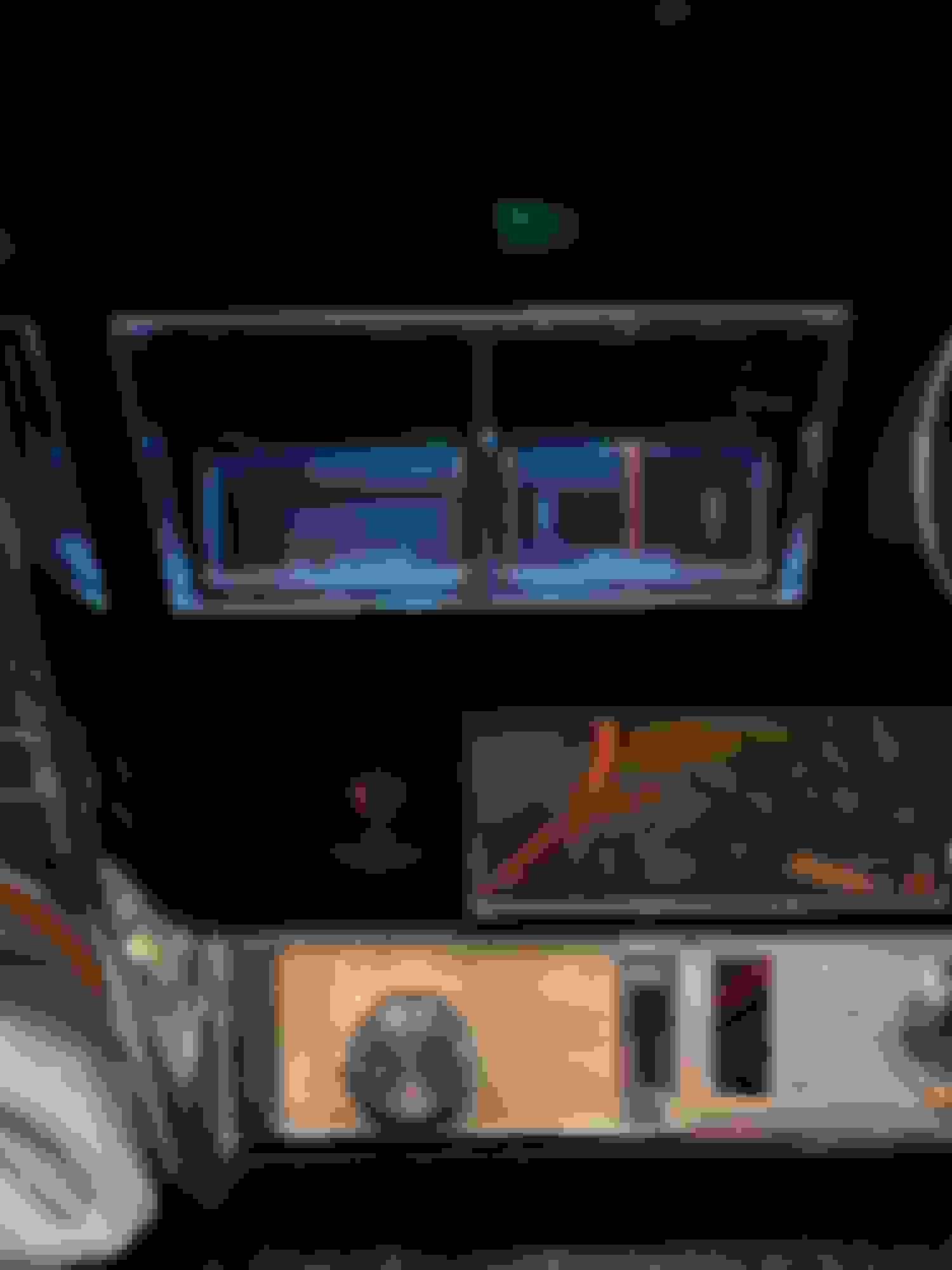
Tested the temp gauge today and it operates exactly as I mentioned earlier. Connect your variable resistance to the "Drk Green" pin labelled in my photo and the rest remain the same. Anywhere from 400 ohms (full cold) down to 40 ohms (full hot) will test the gauge properly.
 January 6th, 2024, 06:49 AM